Thursday, June 6, 2013

Tweaking the G-Code

One of the things I'm not crazy about on the MM2 is the time it takes for the heated bed to get to 70c (which is the temp we're using to print PLA on).  Even at 24V the larger bed takes quite some time to get up there.

I also suffer from a rather short attention span (as many people will testify too).  I'd get my G code all ready, get it loaded into Repetier and manually turn on the bed and extruder.  Invariably I'd get bored waiting and would wander off and get distracted doing something else, only to return 20 mins later to a pool of PLA that had dripped from the extruder.

I'd been looking at various G-Codes and noticed that there is a code that waits for the bed to reach a target temperature.

The M190 command will wait for the bed to get to your target temperature, while M109 will wait for the extruder to get to the target temperature.

With this, I added the following to the Printer Settings/Custom G-code in Slic3r:
M190 S[first_layer_bed_temperature];
M104 S[first_layer_temperature];
G28 X0 Y0;
M109 S[first_layer_temperature];
The first command will turn on the heated bed and wait for it to get to the first layer temperature you've set, while the second command just starts the extruder heating.  I then home X & Y and when that's done I wait for the extruder to reach the first layer temperature with the fourth command.

Now I just hit 'Run' and the printer will do the rest.  No more drippy PLA for me!

Note: You can swap the order of the M104 & M190 commands, the extruder will start to heat up and then the printer will wait on the bed to heat up.  This will reduce the time spent waiting, but you will also have the extruder at temp for most of the time the bed is heating up.  This will probably reduce the amount of PLA in the extruder once the print starts.  Just something to be aware off.

Saturday, June 1, 2013

Installing a bootloader on a Sanguinololu Part 2

I've finally got to the bottom of the issues I was having, and my the FUSE settings on the ATMega1284p where different from the settings I was seeing on a variety of other sources.  I also installed a bootloader that works correctly with the 1284p.

See my first entry on how to setup an Arduino (Mega2560 in my case) as an ISP.  That is still valid.  Do not buy the Sparkfun ISP Pocket Programmer - it cannot handle a chip with more than 64K flash, so it won't work with the 1284p (the bootloader sits in the upper 64k) -- I learnt that when I tried to use it.

I ended up grabbing the bootloader from https://github.com/jmgiacalone/sanguino1284p.  I'm running with the Arduino IDE 1.05 and that bootloader seems to work with it.

I did end up modifying the FUSE settings to match what was on the old ATMega1284p -- in my case, the Sanguinolou board has a 16Mhz crystal on it, and not a Ceramic Resonator.  That's why my FUSE settings are different.  You can see from the pictures below the differences:


Top view of my board - no resonator...
Underside of my board - metal Xtal Oscilator


From reprap.org - the blue 3 wired part is a ceramic resonator


I ended up with the following values for the fuses:

High Fuse: 0xDC, Low Fuse: 0xD7, Extended Fuse: 0xFD

I modified my boards.txt file and added an entry specifically for my board with the crystal oscillator.


atmega1284.name=Sanguinololu W/ ATmega1284p 16mhz

atmega1284.upload.protocol=stk500v1
atmega1284.upload.maximum_size=129024
atmega1284.upload.speed=57600

atmega1284.bootloader.low_fuses=0xd7
atmega1284.bootloader.high_fuses=0xdc
atmega1284.bootloader.extended_fuses=0xfd
atmega1284.bootloader.path=standard
atmega1284.bootloader.file=ATmegaBOOT_1284P.hex
atmega1284.bootloader.unlock_bits=0x3F
atmega1284.bootloader.lock_bits=0x0F

atmega1284.build.mcu=atmega1284p
atmega1284.build.f_cpu=16000000L
atmega1284.build.core=arduino

I found this FUSE calculator page useful in understanding what the different bit combinations actually mean -- http://www.engbedded.com/fusecalc/  -- the one thing I might go back and work on is the boot time -- right now, the board takes a long time to connect to Repetier Host, and I think that's down to the timeout delays in the Boot Loader I'm using. However, I've other things that need sorting first.


Thursday, May 30, 2013

Nylon

Colin has been flooding the blog with a lot of technical posts lately, so I thought I'd jump in with a puff piece.

I finally got around to printing some nylon again. The last time I tried printing with nylon there was a lot of steam and I couldn't get anything to stick to the bed. The nylon filament sucks up a lot of moisture from the air. (Not implying that was the main reason it wouldn't stick but I'm sure it didn't help.) It's been sitting forgotten in a zip lock bag with desiccant for the past few months which probably helped dry it out a bit. I also put down a strip of blue painters tape across the bed. Ended up printing at 235C. Success!

Here's the Stanford Bunny http://www.thingiverse.com/thing:3731 shrunk down to 50mm height.

Wednesday, May 29, 2013

Installing a bootloader on a Sanguinololu (see part 2 for the completion)

While most of the story is described below, part 2 contains the final resolution.

I received my replacement ATMega1284P's from Mouser just before the holiday weekend.  At the same time, I ordered the replacement chips, I ordered a nifty chip puller from Amazon -- it was pretty cheap and with prime, arrived on the same day as the replacement chips.

With everything in hand, I figured this would be a pretty straightforward fix -- boy was I wrong.

I removed the old ATMega from the Sanguinololu board with the chip puller.  I then did something I don't normally do - I thought ahead - and added a sticker to the top of the chip that came out of the socket, that way I can tell it apart from the two new ones... smart eh?

I dropped one of the new ATMegas into the socket and made sure it was correctly seated.  Job done, right, just flash the latest Marlin and off to the races.  Nope - the Arduino IDE would not connect to the Sanguinololu board.  The USB device showed up, but it would never connect.  A little digging on the internet and I discovered that a factory new ATMega1284P does not have a 'boot loader' already installed.  With out the bootloader it's not possible for the Arduino IDE to communicate with the chip over USB.

In order to install a bootloader, I needed to program the chip with a ISP (In System Programming) programmer.  From what I could see, I could buy something that would do the job for me, or I could use another Arduino board to act as an ISP device.  I chose the latter option.

To make this work, connect your Arduino board to your computer and from the Arduino IDE, select File | Examples | ArduinoISP -- this will load a sketch that you can send to your arduino board and let it behave as an ISP device.

From within the loaded sketch, you can see which pins will be used for which purpose.  I was using a Mega2560 board, so the SPI pins where 50,51,52, & 53.


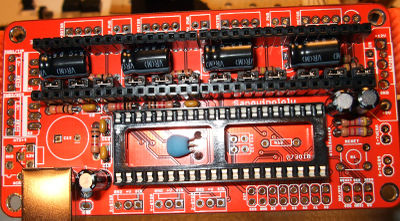
Using jumpers, I connected the Mega2560 directly to the small expansion header labeled SPI/ISP on the Sanguinololu board as indicated below:


The 3 SPI pins and the Reset pin all connect to sockets on the large double rowed digital socket on the ATMega.  I used the ground connection at the end of this connector, along with the 5V pin from the power socket.

I also wired 3 LEDs (as suggested by the Sketch) through a common resistor to ground, with the anode of each LED connected to a single pin on the PWM socket block (7,8, and 9).  The LED connected to pin 9 will pulse off and on when the ISP sketch is running on the ATMega.

Also, when the ATMega resets, each LED will blink quickly in series before settling to the heartbeat pulse.  With this you can see when the ATMega resets, as the 3 LEDs will quickly blink shortly after reset - this turned out to be important.


With everything wired up (and the Sanguinololu disconnected from everything but the Arduino ISP) I had my heart pulse LED, my power LEDs on the ATMega and the power LED on the Sanguinololu all lit up.

Now with the Arduino IDE, I selected the board type as Sanguino w/ATmega1284P 16Mhz and kept the serial port the same as previously.

This is an important note - at this time, you are selecting the type of chip you are installing the bootloader on to, but the serial port is the port the Arduino ISP is connected to.  Only the Arduino is connected to the computer.

<At this point, I suggest you read the section below on modifying your boards.txt file, and don't plough on like I did, only to discover it doesn't work exactly as you want it to>

Now from the Tools menu of the Arduino IDE select Tools | Programmer | Arduino as ISP.

With that done, select the Burn Bootloader from the Tools menu.  This will start burning the selected bootloader onto the ATmega1284p that's connected via SPI to the Arduino board.

It will take a few minutes and you'll see the LEDs you connected to the Arduino flash as the sketch and Arduino IDE do their work.

When complete, the Arduino IDE will indicate success and the heartbeat LED will be pulsing again.  At this point the ATmega1284p will now have the new bootloader installed and you'll be able to upload the printer firmware.

This is where I ran into problems, and hopefully if you're reading this then you can avoid the extra hours of headache I had trying to figure this out...

So it turns out that the default bootloader settings include default FUSE settings.  I've learnt that in micro-controller speak, FUSEs are not what you'd find protecting your toaster oven from setting fire to your kitchen, and that these FUSEs can be 'blown' and then un-blown.  In fact, FUSE is pretty much a crappy name for these things -- if anything they're just a few extra bytes of EEPROM or NVRAM, basically you use them to configure the chip with the ISP.

Furthermore, the ATMega1284P maps the JTAG port onto the GPIO C port when JTAG is enabled, and the C port standard GPIO functions are disabled.  The default FUSE settings leave the JTAG enabled, so your printer firmware will not work.  The axis endstops and x-axis direction pin all share space with the JTAG.  In order to make this work for a printer configuration, you'll need to update your FUSE settings.

The easiest way to do this is to reconnect everything as before so the Arduino is setup to act as a ISP device for the ATMega in the Sanguino board.  However, before programming the device, you should modify boards.txt and update the FUSE settings as follows:
  • low fuse = 0xD7
  • high fuse = 0xDC
  • extended fuse = 0xFD

You'll find boards.txt in the Sanguino folder under hardware.  Go to the bottom of the file and change:

atmega1284.bootloader.high_fuses=0x9A to atmega1284.bootloader.high_fuses=0xDC

This will set bit 6 of the high fuse, which will in turn disable the JTAG function and return port C to your control.

Initially, I investigated the FUSE settings using AVRdude, a command line program that lets you talk to the Arduino and see what's going on under the hood.  For some reason, I had a hard time getting this to work with my Mac, but it worked fine on Windows 7, though this required stopping the auto-reset.

On an Arduino, when you connect to the USB serial port, the device will normally reset.  This was causing the AVRdude problems connecting to the ATMega.  I solved this by connecting a 10uF capacitor between ground and reset (pin 3 on the power connector socket).  This basically acted as a low pass filter stopping the reset pin from going low.

Now when I connected with AVRdude, the ATMega didn't reset and things seemed to work.  One other magic ingredient was the inclusion of '-b 19200' as a parameter.  This allowed AVRdude to actually talk with the Arduino using the serial speed that was set in the ArduinoISP sketch.

I was able to set the FUSE with the following command:


avrdude -p m1284p -c arduino -P com6 -v -b 19200 -U hfuse:w:0xDC:m

-p for the part we're trying to program (a ATMega1284p in this case)
-c for the ISP programmer (an Arduino here)
-P for the com port
-v for verbose mode, so you can see what's going on
-b to set the baud rate (really important!!!)
-U is the actual write command to update the high-fuse.

If you want to test the connection from AVRdude to your target chip, you can leave off the -U and add a -n which will just give you info on the connection but not perform any writes.

Anyway, after sending that command I got the following output:


While this worked, and I was able to get the printer firmware up and running, I'd recommend editing the boards.txt file and setting the hfuse value before the initial flash.

Some photos of the wiring I ended up with:

LEDs, Sanguino & Mega2560
Sanguinololu ISP connection
  
Mega2560 ISP connection
Mega2560 Reset Circuit

Close up of Mega Power connection (white line is reset)

Update:  When I actually tried the board in my printer, it didn't work as expected - Repetier Host was getting a lot of comms errors - I tried messing with the baud rate, and no luck.  Did some more searching and discovered that the FUSE settings I had didn't take the crystal clock into account correctly.  I decided to re-plug in the old working ATMega1284P chip (the one with the dodgy X/Y endstops) and read the FUSE settings from that.  Here's what I got:


As you can see, this is different from what I'd set -- similar, but not the same.  Looking at these bits and the ATmega1284p data sheet, I see the following changes:

For the low fuse: I had a 0xFF and it should be a 0xD7.   This means bits 5 & 3 should be reset. Bit 5 along with bit 4 control the startup time (SUT1,SUT0), while bits 3..0 (CKSEL3...CKSEL0) control the clock source.  In this case a startup-time of 01B with a clock select of 0111B configures the ATMega for a full swing crystal oscillator (which is what is on the sanguinololu board).

For the high fuse: I had 0xDA and it was 0xDC.  In this case, bit 2 is set and bit 1 is reset.  This controls the Boot Size, and while I didn't notice anything different I set it to the previous setting just to be careful.

For the extended fuse: I had 0xFF and it was 0xFD, basically bit should be reset.  This controls the brown out detection level and I did notice a warning when connecting to the Sanguinolou that there had been a brown out reset, which I hadn't seen before.

So to set these new FUSE settings, I could have edited the boards.txt and done it through the Arudino IDE as before, or I could use the following command for AVRdude:


avrdude -p m1284p -c arduino -P com6 -v -b 19200 -U hfuse:w:0xDC:m -U lfuse:w:0xD7:m -U efuse:w:0xFD:m


With this done, I reconnected the sanguinololu up to Repetier host and... (see part 2)


Wednesday, May 22, 2013

MXL Belts & Pulleys

The printer has been using T5 belts with printed pulleys, and they've been working pretty well.  However, we decided to investigate some other belt/pulley options.

The folks at OpenBuilds sell a belt & pulley combo at a pretty reasonable price, so we ordered some up and tried them out.
MXL belt & pulley. The belt pitch is 2.03mm (actually 0.080 inch)

The kit they sell uses an MXL belt, and obviously the pulley to match.  MXL has a belt pitch of 2.03mm, which is the distance between the center of the teeth.  The pulley has 20 teeth, so one revolution of the pulley will move the belt 40.6mm (not 46mm as I had calculated due to my inability to enter 2.03 correctly into a calculator, but enough about that).

We use a stepper motor with a 1.8 degree step angle, so that's 200 steps for one revolution.  The stepper driver is set to 1/16th micro-steps, which means on our setup, 3,200 steps will move the motor one complete revolution.

The firmware we use (Marlin) has a configuration entry for steps per unit:

DEFAULT_AXIS_STEPS_PER_UNIT = {64,64,2560,470};

This was setup for the T5 belt & 10 tooth pulley.  With these, we have 50mm per revolution, and at 3200 steps per revolution, this gives 64 steps per mm.  (3200 / 50 = 64).

The MM2 uses the GT2 belt & pulley.  Here you have a 2mm belt pitch and a 20 tooth pulley, so the steps per mm works out at 80. (3200 / 40 = 80).

With the MXL, we need 78.81773399014778 steps per mm. (3200/40.6 = 78.81773399014778).

I plugged in the new number as the 2nd value (they're in x,y,z,e order) and checked out the results by printing a couple of 20mm x 20mm boxes as vase.

I measured them with our trusty micrometer, and they both measured out to be 19.8 x 19.8.  Slightly smaller than the desired 20 x 20, but not enough to worry about.

We may try some GT2 belts & pulleys and replace the MXL's with those.  That way we don't have to worry about rounding errors, but I don't think the error is that significant anyway.

Update:  After writing this, I went back and checked the values using 2.034 for the pitch (this is what various websites give as the MXL metric pitch).  The value I used inside Marlin was changed to 78.74015748031496.  I ran a couple of test cube prints, and there was no apparent difference in the Y dimensions of the prints, so obviously a pretty small adjustment.  I'd imagine on a larger print it might be more of an issue, but I still couldn't see it being a deal breaker.

Monday, May 20, 2013

Sanguinololu troubles...

We're driving the new printer build with a Sanguinololu board we got in another 3D printer kit (a MM1.5+).  It's not the zippiest board, but it's pretty simple to use and we had it spare.

While doing some test prints, the PLA that was feeding into the extruder decided to grab a bunch of wires and twist them up into itself (my own fault for leaving the PLA coil on the desk).  Of course, I didn't notice this happening until the wires for the X-Stop got pulled off the micro-switch and the printer stopped.

Not only did this ruin the test print, but it seems to have fried the ATMega 644p too.  No matter what I did with the firmware, the endstops for X & Y would not trigger (or un-trigger).


You can see from the photo of the un-populated board, the outer pins are Ground and Sig.  In normal operation, you should see about 5V between these pins, as the Signal line is being pulled up by an internal resistor.  On ours, I was seeing about 2V.  Not right.

Also, with the power off, I measured the resistance between ground and the signal line -- it read 20ohms.  It should be off the scale, i.e. not connected.  Also not good.  So the pulled wire had fried the input pins of both the X and Y end stops.  The Z end stop, which was not connected, behaves as it's supposed to.  It read 5V when being pulled high, and had an open circuit to ground when the board was powered off.  Hooking up a microswitch to that gave the expected results.

We've ordered a new ATMega to replace the existing one - hopefully it comes with the right bootloader and I can just plug it in and flash it with the correct firmware -- fingers crossed!


Friday, May 17, 2013

Pillow block bearing...

We swapped out the LM8's that were on our x-carriage for some pretty cool pillow block bearings we got from Igus.  They're significantly lighter than the metal bearings we'd been using and don't require any lubrication.

They also run quieter and seem to be smoother, both of which can't be bad.


I'm printing a hollow Spocktopus (despite seeing the awful new ST:ID movie I still like that model) to see how it works on a larger complex print.  My previous test boxes all worked out pretty well.


I'll update this with a full pic of the finished print later.